Technical Q&A: Large Fresnel Lens for Solar Concentration

Recently, we received a technical inquiry from a customer regarding our large Fresnel lens (CP1300-1100, focal length 1300mm, PMMA, groove pitch ~0.5mm). Below is a summary of the questions and our answers.


Q. What is the minimum achievable focal spot size?

  • For the CP1300-1100 lens, under ideal conditions, the minimum focal spot diameter is about 6–7 mm.
  • The most critical factor affecting the focal spot size is alignment error.

Q. What are the differences in material types, durability, and the temperature at which deformation or optical degradation occurs?

  • Recommendation:
    • PMMA: Has low weather resistance, weak against scratches, cannot withstand high temperatures, expected lifespan is only 3–5 years. The temperature at the focal spot can reach nearly 1,000°C.
    • SOG: Excellent weather resistance, strong against scratches from wind and sand, high thermal tolerance, usable for over 20 years. The temperature at the focal spot is about 500°C.
  • Maximum temperature at which PMMA lens deformation or optical degradation occurs: about 75°C.

Q. What is possible in terms of custom manufacturing, anti-reflective coating, and surface treatment?

  • Custom design is available upon request with your preferred specifications.
  • The largest manufacturable mold diameter is 2200 mm; actual lens size is 1600 × 1400 mm.
  • Due to the large product size, anti-reflective coatings or special surface treatments are not available.

Preparing the Device Under Test (DUT) for IEC 63180 Compliance

Preparing the Device Under Test (DUT) for IEC 63180 Compliance

Platform: Fresnel Factory Scaled Performance Test (SPT) machine

Overview

IEC 63180 defines test conditions and procedures for evaluating motion detectors based on passive infrared (PIR) sensing.
Fresnel Factory’s SPT machine is a compliant evaluation system that can assess performance using a detector’s
simple on/off event signal; it also supports recording the signal amplitude when needed. For IEC 63180 testing specifically,
the amplitude capture is not required, so your DUT only needs to provide a clean detection (on/off) signal and a common ground.

What the SPT Machine Needs from the DUT

  • Detection Output (on/off): A single digital output that changes state when motion is detected.
    Configure the SPT machine to trigger on the edge (rising or falling) that matches your DUT’s output polarity.
  • Common Ground: Share ground between the DUT and the SPT machine to ensure a stable reference.

Electrical Interface Requirements

The SPT machine accepts logic-high inputs in the range of 3 V to 12 V, so typical 3.3 V or 5 V
PIR module outputs can be connected directly. To maximize signal integrity:

  • Output Level: 3.3 V or 5 V logic is recommended (both are compatible).
  • Drive/Impedance: The SPT input is high impedance (≈10 MΩ), so a standard MCU pin or buffer op-amp can drive it.
  • Damping (optional): A small series resistor (≈100–330 Ω) at the DUT output can reduce ringing on long or noisy runs.

Cabling and Layout Guidance

  • Length: Keep the detection line short—preferably ≤ 1 m—to minimize edge delay and noise pickup.
  • Cable Type: Use twisted pair (signal+GND) and shielding where practical.
  • Environment: During tests, minimize nearby EMI sources (e.g., Wi-Fi radios, high-power LEDs) and thermal disturbances that can influence PIR behavior.

Minimal Wiring: Example

Basic Connections between DUT and SPT Machine
Line DUT Pin SPT Input Signal Type Typical Level
Power VDD (3.3 V or 5 V)
Ground GND GND (shared) Reference 0 V
Detection Motion/Interrupt Output Trigger Input On/Off (edge-triggered) 3–5 V logic

Note: The SPT machine can record signal amplitude if you provide an additional measurement connection. However, IEC 63180 testing does not require amplitude data—only the on/off detection signal is needed.

Pre-Test Checklist

  1. Confirm the SPT input range (3–12 V) matches your DUT output level (3.3 V or 5 V).
  2. Share ground between DUT and SPT; verify a solid, low-noise return path.
  3. Set the SPT trigger edge to match your DUT’s output polarity (rising or falling).
  4. Use short, shielded cabling and tidy routing; add a small series resistor if edges ring.
  5. Allow PIR warm-up time, then verify a clean state transition when motion occurs.

Summary

For IEC 63180, the SPT machine only needs a reliable on/off detection signal from the DUT to evaluate motion-detection performance.
While the platform can also capture amplitude, that feature is optional for this standard. Prepare a clean digital output, keep wiring short and quiet,
and you’ll get repeatable, standards-aligned results with minimal setup.

PIR Sensor Lens Development, Verification, and Mass Production FAQ – Outdoor Camera Development

1. Should PIR lens surfaces be matte or glossy?

The surface finish affects not only the look but also how well the lens works. Glossy surfaces transmit more infrared light, giving the sensor a stronger signal. Matte finishes cut down glare and blend better with product design, which is why many consumer devices use them. In practice, engineers usually polish the actual lens area to be glossy while leaving the non-lens areas either matte or glossy, depending on design goals.

2. How are the lens and housing joined?

For high-volume production, double-sided adhesive tape is the simplest and cheapest option. It holds the lens firmly enough for indoor products. But outdoor cameras face rain and humidity, so additional sealing is common. Depending on the design, engineers add O-rings, cut grooves in the housing, or use waterproof tape and silicone gaskets. In factories overseas, especially in Vietnam, suppliers sometimes deliver lenses with waterproof tape already applied, so assembly workers only need to press the lens in place.

3. What is the impact of adding ribs in mold design?

Ribs around the lens edge make the structure stronger and improve how well the parts stay bonded. The trade-off is that the mold becomes more complex and expensive. Without ribs, the mold is simpler, but the finished product might be weaker or harder to seal against water. Adding ribs also often requires small hook holes, which further raises mold cost. So the decision usually comes down to the waterproof rating required and the target price of the product.

4. How are IP ratings reflected in the design?

If the device is for indoor use, engineers often choose the cheapest option: tape bonding only. Outdoor devices like CCTV units need at least a basic IP rating for dust and water. That means design choices such as grooves, silicone seals, or O-rings must be considered right from the mold design stage. Skipping this step early almost always causes redesign later.

5. What tools are used for PIR lens design?

Designers start with CAD software such as SolidWorks for the mechanical layout. At Fresnel Factory, engineers also run their own calculation tools to predict how the lens will shape the infrared field. After that, ray-tracing simulations check the detection zones, the field of view, and energy distribution. Using both mechanical and optical tools helps catch mistakes early, which saves time and money once molds are made.

6. What standards apply to PIR-based motion detectors?

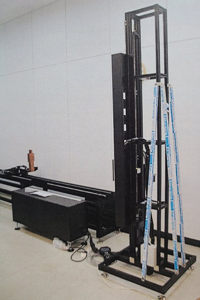
Most companies follow IEC 63180. It defines three key tests: Radial (movement toward the sensor), Boundary (maximum distance and angle), and Tangential (side-to-side motion). These tests are easier to repeat with automated machines than with people walking back and forth. At Fresnel Factory, the Scaled Performance Machine was built to meet IEC 63180, so results are consistent across projects.

7. How much does performance testing cost?

A full set of the three IEC tests costs around USD 2,000. That covers radial, boundary, and tangential measurements. If a customer asks for extra scenarios—for example, testing the sensor at a higher mounting height—those are priced separately.

8. How long does it take to get a test report?

From the time Fresnel Factory receives the sample, testing and reporting usually take about three weeks. That includes running the measurements, reviewing the data, and preparing the report. For urgent projects, the three-week timeline can feel long, so it’s wise to build that time into the project schedule from the beginning.

9. How is the contract typically structured?

Most development contracts require a 50% down payment to begin work. The remaining 50% is due once the customer validates the sample. Mold costs are bundled into the development fee. Although the customer holds the rights to the mold, Fresnel Factory stores and maintains the physical mold and uses it for production. This arrangement is standard in the industry, since it protects quality and avoids problems with mold transfers.

10. Why are 3D modeling files required?

Without a 3D file, designers cannot check how the lens and housing fit together. Customers usually send STEP or IGES files, which show the exterior geometry. From that, engineers create lens patterns, plan mold details, and design seals for waterproofing. Even a basic exterior file is enough to start. Later, once molds are made, prototypes confirm that the design matches expectations. Sharing these files early helps prevent design errors and saves weeks of rework.

11. What materials are used for PIR lenses?

Most PIR lenses are made from Poly FIR200 or its compounded forms like SBK150 and HGW335. Poly FIR200 has good infrared transmission at 8–14 µm and flows well in injection molding. SBK150 is formulated for outdoor use and maintains performance even after years of UV exposure. Accelerated weathering tests show SBK150 still transmits more than 93% of its original level after five years, while cheaper alternatives may drop below 50%.

12. How are lens zones designed?

PIR lenses split the detection area into zones. For example, one design might use three zones covering 35°, 15°, and 7°. This allows the sensor to detect people moving at different heights and angles. If the zones are poorly planned, blind spots appear where motion is missed. That’s why zone design is usually checked both in simulation and in field tests before finalizing.

13. What is the service life of a lens mold?

A well-maintained PIR lens mold can last around four years and produce roughly 150,000 units per year. Actual lifetime depends on the plastic used, production conditions, and how often the mold is polished. Because the lens surface has fine patterns, wear shows up as lower optical performance, not just cosmetic flaws. Regular inspection and light re-polishing extend mold life.

14. How are final product shipment tests carried out?

Before shipment, customers may request a full IEC test or rely on the factory’s own quality checks. Final inspections usually measure detection distance, angle coverage, noise resistance, and waterproofing. In large production runs, even a 0.5% increase in defect rate can mean serious financial loss. For that reason, suppliers and customers should agree on the test scope and acceptance criteria early, before the first shipment leaves the factory.

SPT machin (Scaled Performance Test Machine)

Hello, everyone.

Today, I would like to introduce the unique PIR performance evaluation device developed and fully owned by our company.

The SPT machin (Scaled Performance Test Machine) we developed is a motion detection measuring instrument and has the following strengths.
  • 5-axis CNC automated test system enables motion detection measurement in a 360-degree range at a time
    • Maximum diameter of detection area: 45m (scale ratio 1:5)
  • Maximum sensor mounting height 8.5 m (scale ratio 1:5)
  • The maximum speed of the pile is 25 km/h (15.5 mph) (scale ratio 1:5)
  • Human dummy test according to IEC63180 criteria (scale ratio 1:5)

This device ensures the quality of our products through clear and consistent testing.
That’s why we’re confident that we can provide our partners with high-quality lenses.

Q & A

  • Test target size
    In your previous email you mention 1:5 scale testing dummy(35cm tall per IEC 63180 Figure 7).
    Is this the only testing dummy available? Is a 1:1 testing dummy(175cm tall per IEC 63180 Figure 5) also available?
    > No, we only have 1:5 scale dummy.
  • Facility Shape
    From this presentation, I understand the testing area is circular with DUT at the center, and no other DUT mounting location is possible. Is this accurate?
    >No, our facility can mount DUT for wall-mounted, table-placed and floor-placed. DUT can installed and test as described in there installation manual.
  • DUT Mounting Height
    From this presentation, you mention up to 8.5m mounting height. Is this 8.5m “real” mounting height, or is it 8.5m simulated mounting height per IEC 63180 Table 10?
    According to this Table, H/5 scaling factor can be used when using 1:5 scale testing dummy.
    Can your facility accommodate DUT mounted 8m above the ground, or is the mounting 1.6m above the ground based on h/5 scaling factor?
    >As you well understand about IEC 63180, all the scales are 1:5. DUT installed 1.6meter instead of 8m.
  • Facility Diameter
    Similar to above, is the 22.5 m radius (45 m diameter) “real” distance, or is this simulated distance based on use of 1:5 scale testing dummy?
    >Same as above. 1:5 scale testing.
  • Testing Dummy Movement Speed
    Similar to above is the 25 km/h target speed “real” Linear speed, or is this simulated speed based on use of 1:5 scale testing dummy?
    >Scaled speed. You can find scaled speed in IEC 63180.
  • Speeds for IEC 63180 Motion Prefiles
    Are various speeds possible for the IEC 63180 motion profiles? For example, is it possible to conduct test 7.3.2.2 Radial motion within the detection area at with target moving toward the detector at 1.0m/s, and then repeat the test again with the target moving at 5.5m/s? Results for both speeds will be recorded separately. This speed adjustment is most critical for “Radial Motion” test.
    >Yes, our facility can test different speed and results are recorded separately.

And we use this device to test the performance of the products from other companies.

If you want to know more or get a great product, click here!

paris 2024 olympics

Everyone, the Paris Olympics are in full swing now.
This year’s competition started with a historic opening ceremony on the Seine, and the competition was also full of excitement.
It’s already a few days before the closing ceremony.
After the Olympic Games end, the Paralympics are up next on Aug. 28.

https://olympics.com/en/paris-2024/schedule/11-august

After the women’s basketball game on the evening of the 11th, the Paris Olympics will have its closing ceremony on the 12th.

But there is one surprising fact that we should note here.

The fact is that the fresnel lens we use was first developed in France in 1821.
The Fresnel lens is one of the condensing lenses that collects light like a convex lens, but it has become thinner.
Thanks to its thinned thickness, it is now used in many fields.
As a case in point, Fresnel lenses are used in lighthouses, doorbells, sensors in infrared cameras, and our company manufactures lenses of various colors to accommodate a wide range of customer requirements, ranging from design.
The PIR or TMOS sensors are also very suitable lenses for regulations such as California Title 24, as they serve as off-sensors for energy conservation in new buildings.

Do you have any more questions about the fresnel lens?
If so, click here!

Bring Fresnel Factory Korea to the World!

FRESNEL FACTORY Inc Participated in SENSORS CONVERGE 2024.

JULY 15, 2024


everyone, Our company participated in the SENSORS CONVERGE 2024 held in Santa Clara, California, for three days from June 24 to June 26.

Following last year, many companies participated and visited this event, and our company was able to successfully market.

Many guests came to our Fresnel Factory Korea booth (#823).

We will be a good business partner!

Ashton MYUNG JOONG KIM, CEO of Fresnel Factory Inc, who is explaining the product to booth visitors

Our booth(#823) DETAILS

List of companies that visited FRESNEL FACTORY Inc. at this event.

STAY TUNED FOR MORE UPDATES, AND WE HOPE TO SEE YOU THERE!

CONTACT INFORMATION:

ASHTON MYUNG JOONG KIM
CEO OF FRESNELFACTORY INC.
USA: +1 415 779 5317
MOBILE: +82 10-5248-4630
ASHTON@FRESNELFACTORY.COM

Join Us

Get your best customized products.

We own all the programs from the initial design of the Fresnel lens to the final verification.

Fresnel Factory Official Logo

Step of one Stop Service.
Fresnelfactory Korea Inc. Provides One-stop Service for your needs for optics.
If you concern about time and budget, we can provide you Fast-track to find out best solution from our existing products.

  1. Planning : To find out the needs of customer and set-up constraints.
  2. Design : Optical design and simulation-based on details and constrains.
  3. Test : To check the assumption from the design stage and find out best solution from existing products.
  4. Mold design : To check the assumption from the design stage and Hot press or injection mold
  5. Production
  6. Quality inspection
  7. Delivery

You can access the Fresnel Factory official site for more information.