
Author: Myungjoong Kim, CEO, Fresnel Factory Inc.
Reading Time: Approximately 10 minutes
Quick Answer
SWIR and the infrared band used by PIR motion sensors are both outside the visible spectrum, but they operate as almost entirely different technologies.
- SWIR systems typically operate from approximately 0.9 to 1.7 µm and usually image reflected or transmitted light.
- PIR motion sensors typically detect thermal radiation near 8–14 µm, which is more accurately described as LWIR or thermal infrared.
- SWIR commonly uses InGaAs detectors, while PIR sensors use pyroelectric elements.
- A SWIR system may require sunlight, an LED, or a laser illuminator. PIR sensors detect radiation emitted by people without active illumination.
- SWIR and 8–14 µm systems require different detectors, optical materials, lens geometries, manufacturing tolerances, and evaluation methods.
The term “FIR lens” is widely used in the PIR motion-sensor industry, but specifying the actual operating wavelength—usually 8–14 µm—is more technically accurate.
“`
Why Is the Term “FIR” Confusing in the PIR Industry?
“`
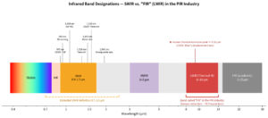
Infrared wavelength terminology is not completely harmonized across optics, remote sensing, thermal imaging, telecommunications, and sensor manufacturing.
A practical engineering classification is:
| Band | Common Practical Range | Typical Applications |
|---|---|---|
| NIR | Approximately 0.75–1.0 µm | 850 nm and 940 nm illumination, 905 nm LiDAR, ToF, and 3D sensing |
| SWIR | Typically 0.9–1.7 µm | InGaAs imaging, inspection, spectroscopy, and 1,550 nm systems |
| Extended SWIR | Up to approximately 2.5–2.6 µm | Chemical analysis and extended-InGaAs detection |
| MWIR | Approximately 3–5 µm | Cooled thermal imaging and high-temperature measurement |
| LWIR / thermal IR | Approximately 8–14 µm | PIR sensing, uncooled thermal cameras, and thermopiles |
| FIR | Definition varies by field | Frequently used informally for 8–14 µm PIR lenses |
NASA Earth Science refers to 8–15 µm as thermal infrared because this region is useful for observing long-wave thermal energy emitted by the Earth. NASA’s remote-sensing classifications also include SWIR bands near 1.55–1.75 µm and 2.08–2.35 µm, illustrating why SWIR definitions may extend beyond the standard InGaAs range.
Source: NASA Science
For engineering specifications, it is therefore better to write:
- 8–14 µm PIR Fresnel lens
- LWIR thermal-imaging lens
- 0.9–1.7 µm SWIR lens
rather than relying only on the term “FIR.”
At Fresnel Factory, the product terminology can be understood as follows:
- Poly NIR series: Materials and lenses intended for selected near-infrared wavelengths such as 850, 905, 940, and 1,050 nm.
- Poly FIR series: Polyethylene-based Fresnel lenses generally intended for human-detection applications near 8–14 µm.
Fresnel Factory provides separate categories for
PIR motion-detector Fresnel lenses
and
NIR and FIR optical components.
These categories should not be treated as interchangeable simply because both involve infrared wavelengths.
A material that performs well at 905 or 940 nm should not automatically be assumed to transmit efficiently at 1,310 or 1,550 nm. Spectral transmission must be verified across the wavelength range of the actual detector and illumination source.
“`
What Is the Main Difference Between SWIR and PIR Thermal Infrared?
“`
The most important difference is the origin of the radiation being detected.
| Parameter | SWIR | PIR-Industry “FIR” |
|---|---|---|
| Full name | Short-Wave Infrared | Usually an informal name for LWIR or thermal IR |
| Typical operating range | 0.9–1.7 µm | 8–14 µm |
| Broader definitions | May extend from approximately 0.7 to 2.5 µm | FIR boundaries vary considerably by field |
| Main radiation source | Reflected or transmitted sunlight, LED, or laser radiation | Thermal radiation emitted by people, animals, and objects |
| Representative detector | InGaAs, extended InGaAs, selected HgCdTe detectors | Pyroelectric PIR, microbolometer, and thermopile |
| Typical applications | Inspection, spectroscopy, moisture detection, wafer inspection, and laser imaging | Motion detection, occupancy sensing, thermal imaging, and temperature measurement |
| Ordinary glass | Some glass types can be used over selected SWIR bands | Ordinary window glass is generally opaque at 8–14 µm |
| Common optical materials | Selected optical glass, fused silica, silicon, and chalcogenide | Polyethylene, germanium, ZnSe, ZnS, and chalcogenide |
| Active illumination | Frequently used | Not required for human thermal-radiation detection |
| Primary image information | Reflectance, transmission, and absorption | Surface temperature, emissivity, and thermal contrast |
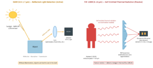
SWIR behaves more like visible-light imaging than conventional thermal imaging. Objects reflect, transmit, or absorb SWIR photons, and these differences create image contrast.
By contrast, PIR sensors and LWIR thermal cameras primarily detect energy emitted by objects because of their temperature.
“`
Which Wavelengths Are Commonly Used in SWIR Systems?
“`
A standard InGaAs detector generally covers approximately 0.9–1.7 µm. A representative Hamamatsu InGaAs photodiode specifies a cutoff wavelength of 1.7 µm and a typical peak-sensitivity wavelength of 1.55 µm.
Source: Hamamatsu Photonics
| Wavelength | Common Classification and Application |
|---|---|
| 850 nm | NIR illumination and sensing |
| 905 nm | Usually treated as NIR in LiDAR and ToF systems |
| 940 nm | NIR illumination, facial sensing, and 3D sensing |
| 1,050–1,064 nm | Boundary between NIR and SWIR terminology; industrial lasers |
| 1,310 nm | SWIR telecommunications and optical measurement |
| 1,450 nm | Strong water-absorption region |
| 1,550 nm | Telecommunications, eye-safer LiDAR, and SWIR imaging |
| Approximately 1,900 nm | Strong moisture-sensitive spectral region |
| 2.0–2.5 µm | Spectroscopy and chemical identification |
The classification boundaries overlap. For example, a 905 nm detector may technically fall within a broad SWIR definition, but most LiDAR engineers refer to 905 nm as NIR. For this reason, the wavelength itself should always be included in the product specification.
Extended-InGaAs detectors can reach longer wavelengths than conventional InGaAs devices. However, the detector material, optical material, coating, and illumination source must all be selected for the same spectral range.
“`
How Does a SWIR Camera Form an Image?
“`
Most SWIR cameras form images through a process similar to visible-light cameras:
- Sunlight, ambient radiation, a SWIR LED, or a laser illuminates the object.
- The object reflects, transmits, or absorbs different portions of the spectrum.
- The remaining radiation passes through the optical system.
- An InGaAs detector converts photons into electrical signals.
- The system produces a grayscale, multispectral, or hyperspectral image
Unlike a PIR sensor, a conventional SWIR camera does not normally detect a room-temperature person primarily from body heat. It usually detects sunlight, ambient nighttime radiation, or active illumination reflected from the person.
Hot metal, flames, furnaces, and molten materials can emit significant radiation in the SWIR band. However, that is a high-temperature application and should not be confused with ordinary human detection at room temperature.
“`
Why Do PIR Sensors Use Approximately 8–14 µm?
“`
The thermal-emission peaks of people and ordinary indoor objects therefore fall near 9–10 µm. This is one reason PIR sensors and uncooled thermal-imaging systems commonly operate in or near the 8–14 µm atmospheric window.
NASA describes 8–15 µm as a thermal-infrared region suitable for observing long-wave thermal radiation.
Source: NASA Science
The PIR sensor does not require an infrared LED or laser because the person is already the radiation source. This is the meaning of passive in Passive Infrared.
“`
How Is a PIR Sensor Different from a Thermal Camera?
“`
PIR sensors, microbolometer cameras, and thermopiles may all respond to thermal infrared, but they produce different types of information.
How Does a PIR Sensor Work?
A PIR sensor normally uses one or more pyroelectric elements. When the amount of infrared radiation reaching an element changes, the temperature and polarization of the pyroelectric material change, producing an electrical signal.
This expression means that a PIR sensor is primarily sensitive to a change in incident infrared flux, rather than a constant absolute temperature.
Murata explains that a pyroelectric sensor produces an output when the temperature of its pyroelectric ceramic changes. When the ceramic temperature remains stable, it does not continue to produce the same detection output.
Source: Murata Manufacturing
This explains several PIR characteristics:
- A stationary person can become difficult to detect after the initial signal.
- Movement across detection zones produces alternating signals.
- Lens segments determine the direction and spatial distribution of the detection zones.
- Amplifier bandwidth and digital detection algorithms strongly affect performance.
How Does a Microbolometer Work?
A microbolometer contains a two-dimensional array of pixels. Incident thermal radiation changes the temperature and electrical resistance of each pixel.
The camera can therefore produce a thermal image rather than a simple motion signal. With appropriate calibration, it may also estimate surface temperature.
Commercial LWIR camera lenses and modules are commonly designed for approximately 8–14 µm operation.
Source: Teledyne FLIR OEM
How Does a Thermopile Work?
A thermopile converts the temperature difference created by incident radiation into a thermoelectric voltage.
Thermopiles are commonly used in:
- Non-contact thermometers
- Occupancy and presence sensors
- Low-resolution thermal arrays
- Gas-analysis instruments
- Appliance and industrial temperature sensing
Unlike a typical PIR element, a thermopile can respond to relatively steady thermal flux, although its response speed, sensitivity, and spatial resolution depend on the detector structure and signal processing.
“`
What Information Does SWIR Imaging Reveal?
“`
SWIR imaging shows differences in spectral reflectance, transmittance, and absorption.
Depending on the wavelength and material, SWIR can reveal:
- Moisture-content variations
- Bruising or defects in fruit and agricultural products
- Contaminants in food-processing lines
- Features beneath selected inks or coatings
- Defects in solar cells
- Structures through silicon wafers
- Differences between polymers, textiles, minerals, and chemicals
- Laser spots that are invisible to the human eye
NASA’s remote-sensing systems use SWIR bands to identify differences in leaf water content, minerals, soil characteristics, and other material properties.
Source: NASA Landsat
A SWIR image often resembles a monochrome visible-light image because it can include shadows, reflections, and illumination non-uniformity. However, objects with similar visible colors may appear very different when their SWIR absorption spectra differ.
“`
What Information Does an 8–14 µm Thermal System Reveal?
“`
An LWIR thermal image is affected by:
- Surface temperature
- Surface emissivity
- Reflected thermal radiation
- Thermal conductivity
- Thermal capacity
- Heat flow
- Temperature changes over time
- Thermal contrast between a target and its background
Two objects with the same visible color can appear very different in a thermal image when their temperatures or emissivities differ.
Conversely, objects with different visible colors may look similar in an LWIR image when their surface temperatures and emissivities are similar.
This distinction is important when selecting a detector. SWIR is usually selected to identify material or spectral differences, while LWIR is selected to identify thermal differences.
“`
Why Are SWIR and LWIR Lens Materials Different?
“`
Optical transparency is wavelength-dependent. A material that appears transparent to the human eye may be opaque at another infrared wavelength.
Which Materials Can Be Used for SWIR Optics?
For a conventional 0.9–1.7 µm system, candidate materials may include:
- Selected optical glasses
- Fused silica
- Silicon
- Sapphire
- Chalcogenide glass
- Selected SWIR-transmitting polymers
- Crystalline infrared materials
SWIR optics generally use optical designs similar to visible-light systems, but the glass selection, anti-reflection coating, and chromatic correction must be optimized for the actual spectral range.
A visible-light lens may physically transmit part of the SWIR spectrum while still producing poor image quality because its focus shift, coating, aberration correction, and material absorption were not designed for that band.
Which Materials Can Be Used at 8–14 µm?
Typical LWIR optical materials include:
- Germanium
- ZnSe
- ZnS
- Chalcogenide glass
- Selected infrared crystals
- Polyethylene-based materials
Ordinary window and camera glass is unsuitable for most 8–14 µm applications. Special infrared-transmitting optical materials are therefore required.
High-resolution thermal cameras usually require precision germanium, chalcogenide, or other engineered infrared optics.
PIR motion detectors have different requirements. They normally prioritize:
- Low manufacturing cost
- Wide field of view
- Detection-zone segmentation
- Thin-wall construction
- High-volume production
- Outdoor durability
- Suitable transmission near the human thermal-emission band
For these reasons, thin polyethylene-based Fresnel lenses are widely used in PIR motion sensors.
Fresnel Factory develops
wavelength-specific optical polymer materials,
including Poly NIR212, Poly FIR200, and Poly FIR25. The material must be selected according to the operating wavelength, required transmission, mechanical properties, environmental conditions, color, and molding process.
For a more detailed comparison of polyethylene compounds used in human-detection optics, see the
Guide to Material Selection for 8–14 µm FIR Lenses.
The guide discusses factors including infrared transmission, thickness attenuation, UV resistance, and compounded color materials.
“`
How Does SWIR Fresnel-Lens Design Differ from PIR Fresnel-Lens Design?
“`
The design objective changes significantly between the two applications.
What Is a SWIR Fresnel Lens Designed to Do?
A SWIR Fresnel lens may be developed for:
- Concentrating radiation onto an InGaAs detector
- Collimating a 1,310 or 1,550 nm source
- Coupling light into a detector array
- Spectrometer entrance optics
- Structured illumination
- Non-imaging collection
- Compact low-resolution imaging
Important design parameters may include:
- Spot size
- Numerical aperture
- Detector active area
- Working distance
- Focal length
- Chromatic focal shift
- Wavefront error
- Modulation transfer function
- Stray light
- Fresnel reflection loss
- Groove profile and surface roughness
Because SWIR wavelengths are relatively short, groove rounding, tool marks, surface roughness, and dimensional errors can introduce scattering and reduce concentration efficiency or image quality.
A Fresnel lens is not automatically suitable for every SWIR camera. A precision refractive lens may be more appropriate when high image resolution and low distortion are required.
What Is a PIR Fresnel Lens Designed to Do?
A PIR Fresnel lens is normally not intended to create a sharp image.
Its primary functions are to:
- Divide a field of view into multiple detection zones
- Direct each zone onto a pyroelectric element
- Generate alternating signals as a target moves
- Create near, middle, and far detection patterns
- Establish wall-mount, ceiling-mount, or curtain patterns
- Control blind spots and overlap
- Match dual- or quad-element sensor geometry
- Provide the required horizontal and vertical field of view
The PIR lens therefore behaves more like a field-mapping optic and spatial modulator than a conventional imaging lens.
“`
Can SWIR Be Used to See Heat?
“`
SWIR is infrared radiation, so it is not completely unrelated to temperature. However, it is generally unsuitable for observing thermal radiation from room-temperature people or objects.
A person near 310 K has a peak thermal-emission wavelength of approximately 9.35 µm. Thermal emission at 1.55 µm is extremely small by comparison.
A typical SWIR image of a person therefore shows:
- Reflected sunlight
- Reflected ambient nighttime radiation
- Reflected SWIR LED radiation
- Reflected 1,064 or 1,550 nm laser radiation
An 8–14 µm thermal camera or PIR sensor, by contrast, detects radiation emitted by the person and can operate without active illumination.
SWIR can be used for thermal measurement when the target is sufficiently hot, such as:
- Molten metal
- Furnaces
- Flames
- Hot glass
- Semiconductor processes
- High-temperature industrial components
In those cases, the target temperature shifts a meaningful portion of its thermal emission toward shorter wavelengths.
“`
When Should an Engineer Select SWIR?
“`
SWIR is appropriate when the system needs to:
- Detect moisture-content differences
- Inspect features beneath selected coatings or inks
- Examine silicon wafers or photovoltaic cells
- Detect a 1,310 or 1,550 nm laser
- Perform food or agricultural sorting
- Identify chemical or material differences
- Build a SWIR spectrometer
- Align an invisible laser
- Receive a LiDAR signal
- Improve imaging performance in selected haze, smoke, or low-light conditions
- Use active illumination in approximately the 0.9–1.7 µm range
Performance through fog or smoke is not universal. It depends on wavelength, particle size, water content, atmospheric path length, and illumination power.
“`
When Should an Engineer Select PIR or LWIR?
“`
An 8–14 µm PIR or LWIR system is appropriate when the system needs to:
- Detect human movement without active illumination
- Detect occupancy at night
- Produce a thermal image
- Measure surface temperature
- Inspect electrical overheating
- Detect fires or hot spots
- Control HVAC or building lighting
- Detect animals
- Perform perimeter surveillance
- Identify thermal leakage or insulation defects
A PIR detector is normally preferred for low-cost motion detection.
A microbolometer is preferred when spatial thermal information or an image is required.
A thermopile is preferred when absolute or slowly changing radiation measurements are more important than motion-zone detection.
“`
How Can Polymer Fresnel Optics Be Used for Thermal Imaging?
“`
Polyethylene Fresnel optics can also be considered for compact, low-cost thermal-imaging systems where the required image resolution, field of view, detector format, and environmental conditions allow their use.
Fresnel Factory has developed an
HDPE lens module for 9–14 µm thermal-imaging sensors.
The prototype module uses HDPE and was developed with an 8 mm focal length and a 20° field of view for evaluation with a thermal-imaging sensor.
The company also published an evaluation using a
FLIR Boson 320 sensor with an HDPE Fresnel lens module.
This application demonstrates how molded polymer optics may be evaluated as an alternative to conventional precision infrared lens assemblies in selected compact thermal-camera designs.
Polymer Fresnel lenses are not a direct replacement for germanium or chalcogenide optics in every thermal camera. The acceptable solution depends on:
- Detector resolution and pixel pitch
- Required MTF and image quality
- Focal length and field of view
- Environmental temperature range
- Lens thickness and transmission
- Stray radiation and internal reflections
- Mechanical packaging
- Target manufacturing cost
“`
How Should a SWIR Detector Company Evaluate a Fresnel-Lens Supplier?
“`
A SWIR detector company should not evaluate a potential supplier only by asking whether it already manufactures “infrared lenses.”
The supplier should be able to define and verify:
- The exact wavelength or spectral band
- The detector material and active-area dimensions
- Whether the system is imaging or non-imaging
- The illumination source and beam characteristics
- The required field of view or numerical aperture
- The focal length and working distance
- The target spot size or energy distribution
- Material transmission across the complete operating band
- Surface-roughness and groove-profile requirements
- Environmental and production-volume requirements
Experience with 8–14 µm PIR optics does not automatically prove capability at 1,550 nm. Conversely, a material developed for 940 nm NIR sensing may not be suitable for a broadband 0.9–1.7 µm SWIR camera.
The wavelength-dependent refractive index, absorption, molding characteristics, coating requirements, detector architecture, and required image quality must all be reviewed.
“`
How Can Fresnel Factory Support SWIR and PIR Optical Development?
“`
Fresnel Factory’s established PIR capabilities include:
- 8–14 µm polyethylene Fresnel-lens design
- Human thermal-radiation collection
- Wide-field detection-zone mapping
- Dual- and quad-element pyroelectric sensor optics
- Wall-mount, ceiling-mount, and curtain detection patterns
- Injection-molded thermal-infrared optical components
- Optical simulation and sensor performance testing
For a SWIR project, the development process should begin with the wavelength and system architecture rather than by reusing an existing PIR design.
Potential development support includes:
- Material-transmission review for the target wavelength
- Detector-coupling optical design
- Fresnel concentrator design
- Laser collimation or beam shaping
- Detector-array coupling
- Moldability and tolerance review
- Prototype tooling
- Injection-molding process development
- Optical and system-level performance testing
Fresnel Factory’s
lens simulation and system design consultancy
supports the definition of the field of view, sensing distance, detector geometry, material, mechanical integration, and expected system performance. Optical design should begin before the external product design is finalized because the lens size, shape, and exposed optical area can affect both performance and industrial design.
Once the optical concept has been validated, the design can be transferred to
mold tooling, prototyping, and volume manufacturing.
This process includes converting the optical surface into a manufacturable mold design, reviewing post-molding shrinkage, selecting a suitable material, and controlling the mechanical tolerances between the lens, housing, and detector.
Manufactured optics and completed sensor assemblies can also be evaluated through
optical performance testing for infrared sensing devices.
The test service is intended for motion, presence, and LiDAR applications and can be used to compare simulation results with the performance of the manufactured device.
A Fresnel optical element can be effective when the objective is compact light collection, beam shaping, collimation, field mapping, or non-imaging concentration. For high-resolution SWIR imaging, the benefits and limitations of Fresnel optics should be evaluated against conventional multi-element refractive optics.
“`
Frequently Asked Questions
“`
Is SWIR the Same as Thermal Imaging?
No. SWIR normally forms an image from reflected or transmitted radiation, while thermal imaging normally detects radiation emitted by an object because of its temperature.
Is 905 nm Considered SWIR?
It falls within some broad SWIR definitions, but most LiDAR and sensing engineers classify 905 nm as NIR. Specifying the wavelength is more reliable than relying only on the band name.
Is 1,550 nm Considered SWIR?
Yes. A wavelength of 1,550 nm is within the conventional 0.9–1.7 µm SWIR range and is commonly detected using InGaAs devices.
Why Is an 8–14 µm PIR Lens Called an FIR Lens?
The term developed as an industry convention. More precise descriptions are “8–14 µm PIR lens,” “LWIR PIR lens,” or “thermal-infrared PIR lens.”
Can an Ordinary Glass Lens Be Used for SWIR?
Selected glass types can be used over portions of the SWIR spectrum. However, transmission, coating, focus shift, and aberration performance must be verified over the actual operating band.
Can Ordinary Glass Be Used for an 8–14 µm Thermal Camera?
Generally, no. Ordinary window and camera glass is largely opaque in this band, so infrared materials such as germanium, chalcogenide glass, or selected polymers are required.
Why Does a PIR Sensor Have Multiple Fresnel Segments?
Each segment maps a different region of space onto the pyroelectric elements. A moving target crosses these regions and creates the changing or alternating infrared signal required for motion detection.
Can One Fresnel-Lens Material Support Both 940 nm and 1,550 nm?
Possibly, but it should not be assumed. Transmission, refractive index, absorption, surface quality, and molding performance must be verified at both wavelengths.
“`
Conclusion
“`
SWIR and PIR thermal infrared should not be treated as interchangeable simply because both are called infrared.
A SWIR system near 0.9–1.7 µm generally observes reflected, transmitted, or actively illuminated radiation. A PIR or LWIR system near 8–14 µm detects thermal radiation emitted by people and objects.
This difference determines:
- Detector technology
- Illumination requirements
- Optical materials
- Lens geometry
- Manufacturing tolerances
- Test methods
- The information contained in the resulting signal or image
When discussing a new infrared optical project, the most useful first question is therefore not:
“Is this an IR lens?”
It is:
“What is the exact operating wavelength, detector type, and optical function?”
“`
Discuss Your Infrared Optical Requirements
“`
Engineers can review Fresnel Factory’s standard components through the
Fresnel Factory supplier page on DigiKey.
For custom SWIR, NIR, PIR, thermopile, or thermal-imaging optics,
contact Fresnel Factory
with the following initial requirements:
- Operating wavelength or spectral range
- Detector model and active-area dimensions
- Imaging or non-imaging application
- Required field of view
- Detection or working distance
- Available lens dimensions
- Target material and environmental conditions
- Prototype and expected production quantities
Fresnel Factory operates from its head office in Suwon, South Korea, with a U.S. branch in Silicon Valley.
“`